Car: 2001 Neon RT 120Km First Mod.
Purpose: Remove Catalytic converter and replace with 2.5 pipe.
Motor Mount inserts recommended because of no flex pipe.
Materials:
3ft 2.5 exhaust pipe, (Greggs Distributers - $15)
2X 18mm X 1.5 pitch Metric Nut (Bolt Supply $1.50)
1X 2.5 inch Exhaust Clamp (On hand)
1X 4in X 4in .375 inch thick steel (Scrap)
1X Package of 18mm defoulers
Tools:
Metric wrenches & sockets
Hack Saw or Grinder (with zip cut disk)
Drill,
Drill Bits 3/4 , ½ , 3/8
Welder
Plasma / Torch / or 2.5 hole saw & lots of cutting fluid.
Procedure:
1) Jack up car and remove down pipe & cat off of manifold.
a. WD40 or equivalent all bolts & nuts to be removed!
b. Remove exhaust clamp (15mm wrench)
c. Remove 2 oxygen sensors (7/8 wrench), I did not unclip the wires just twisted them carefully.
d. Remove bracket holding downpipe on exhaust manifold 4 bolts (10mm, 13mm 15mm, 18mm wrench’s)
e. Remove the remaining 3 bolts connecting downpipe to exhaust manifold (13mm wrench)
f. Remove bottom of downpipe out from the rest of the exhaust (takes some wiggling) then remove downpipe & cat.
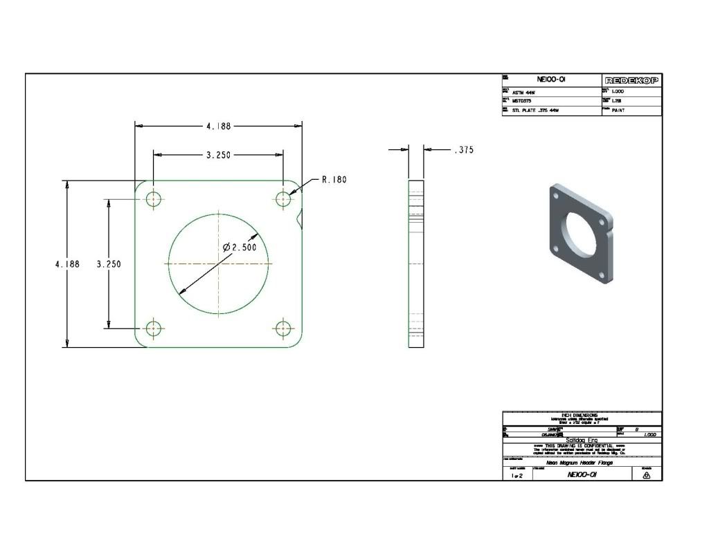
2) Make exhaust flange.
http://i852.photobucket.com/albums/ab87 ... -01_R0.jpg
a. Cut a 4in by 4 inch square out of 3/8 steel. Cut holes in it to match the flange on the downpipe/cat that was removed. Or make it the same as the drawing attached below.
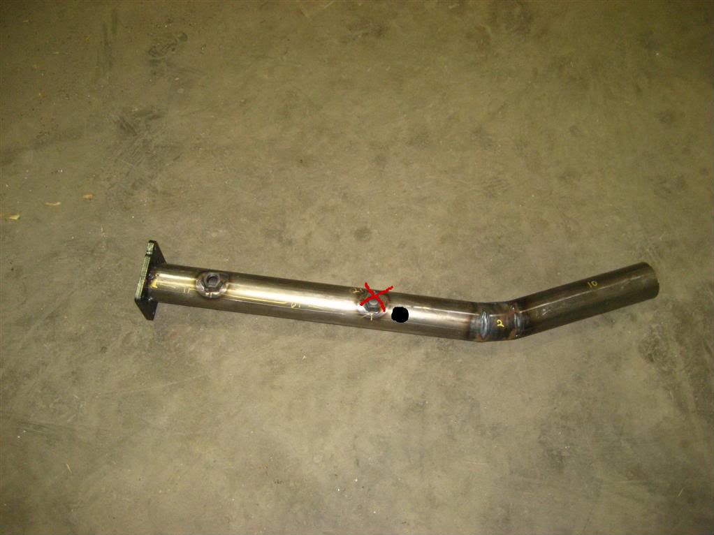
3) Cut exhaust tubing
http://i852.photobucket.com/albums/ab87 ... 3686-1.jpg
a. Take the 3 ft piece of 2.5 in pipe and draw straight line down it. (This is very helpful for later on)
b. With the line facing straight up mark 21.5 inches. Cut at 6 deg angle, the line being the center of angle. (See pictures if you don’t understand 2 extra flanges in picture )
c. Next measure 2.0 inches and cut at 6 deg the other way making a wedge shape piece. (See pic if you don’t understand)
d. Mark and cut the last piece to 10in this cut with be at 90deg because you should have one 6deg edge left from the last cut. (Again see picture…)
e. On a flat table line up the line you drew on the pipe to make 2X 12 deg corners, Your line should line up perfectly, then there is no guessing. Tack and weld pipe. Be careful not to burn holes.
4) Fit the flange on the 21.5 end of the welded together pipe, put 1 tack on the flange to the pipe, (PS: the pipe went through my flange flush with the other side) Now hold up to exhaust manifold. Cut tack and twist pipe in flange until you get a perfect fit, mark it, tack it, fit it up again… This is a little trial and error; make sure your flange is flat against the exhaust manifold. Once good weld it up. (Also mark spots for O2 sensors, read next step)
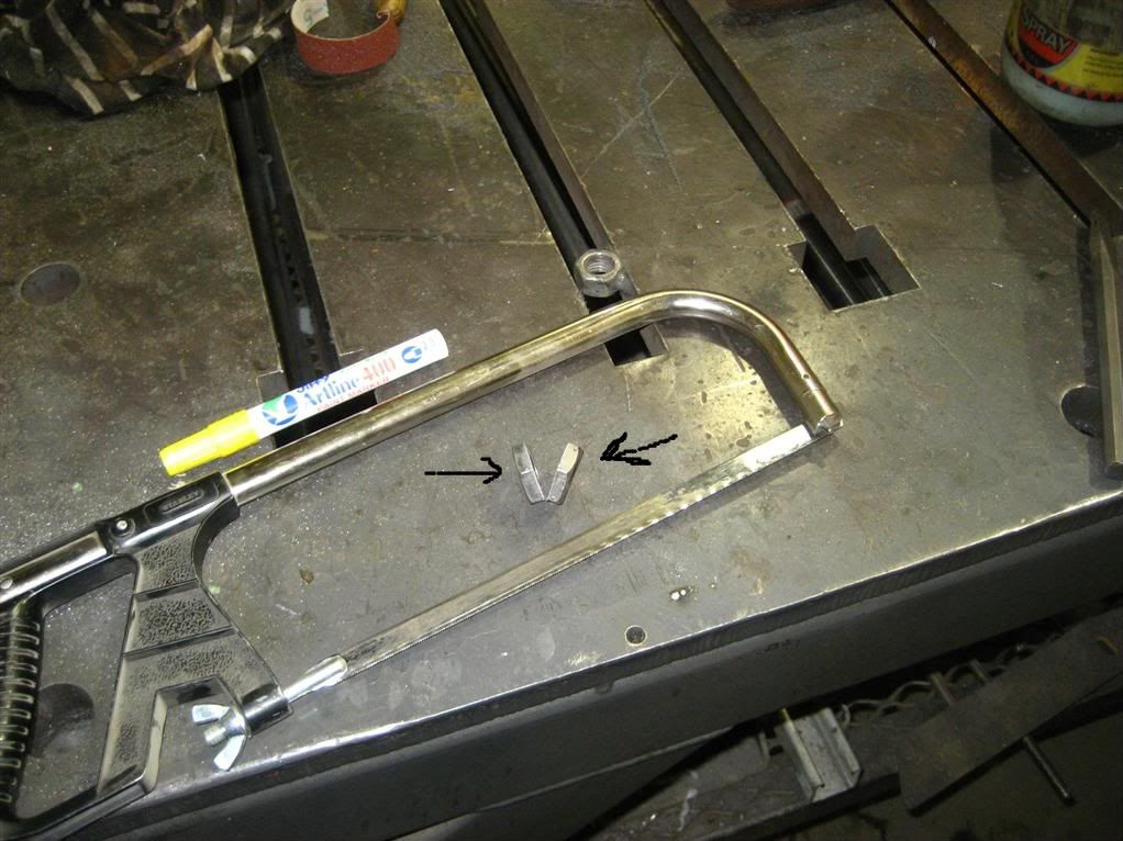
5) Add Oxygen Sensor holes.
http://i852.photobucket.com/albums/ab87 ... arge-1.jpg
a. Drill 2 X ¾ inch or slightly larger holes one 4inches down from the flange and one 14 inches from the flange. (Use the angles marked from previous step)
b. Take 18mm nut and cut in half with hack saw so it isn’t so thick, I use a grinder to remove about 1/3 of the thickness of the nut. ( I did this because I figured it would be good if the O2 sensor was inside the tube like the factory one,)
http://i852.photobucket.com/albums/ab87 ... arge-1.jpg
c. Center nuts so that the threads don’t hit the tube, if the threads hit the tube you will screw up the threads on your defoulers, like I did or possible O2 sensors.
6) Assemble almost exactly the same as removal
a. Remove old exhaust clamp, this is done because our new downpipe now fits overtop instead of inside. The clamp is welded onto the factory exhaust in one spot opposite the bolt. Take a drill with the ½ inch drill and drill the weld out. With a hammer tap the clamp off.
b. Fit the new downpipe on starting with the flange then the pipe. During this stage you should not have any bolts in place. Also make sure your exhaust gasket is in place.
c. Now bolt everything together. Use 2 defoulers on O2 sensor, ( Google this if you have never done it. )
Comments: Exhaust is noticeably louder,
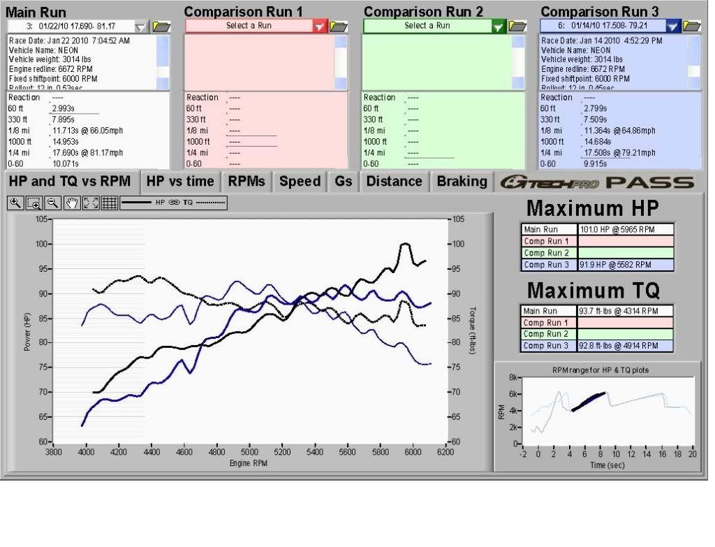
Gtech Dyno run on its way. Before & After
http://www.gtechprosupport.com/support/ ... ing-HP.pdf
So far no CEL with defoulers
I didn’t put a flex pipe in because they are about $40-$60 and figured I would try without one. Put one in if you want.
How To: 2.5 Downpipe / Cat removal Neon RT DIY
Gtech runs
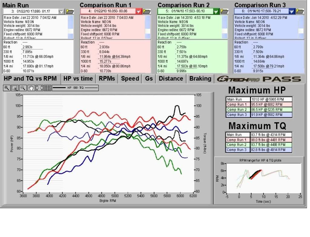
Again if you don't know how a GTech calculates hp please look at the link posted above. These runs were done not for 1/4 mile times but for HP and Torque measurements. ...it was icy out therefore I could not launch well.
Best Mod Run Vs Best Stock Run
http://i852.photobucket.com/albums/ab87 ... stPipe.jpg
2 Mod runs Vs 2 Stock runs
http://i852.photobucket.com/albums/ab87 ... NeonRT.jpg
-
BlackRoseRacing

- 2009 Platinum Contributor
- Posts: 12737
- Joined: Sat Dec 25, 2004 8:58 am