Recently, my AEM AFR gauge started going crazy due to a fried harness. I took it apart, completely since it's the old style with the harness built into the gauge, and replaced the harness. While looking at the circuit boards, I wondered if you could remotely wire the 3 digital number blocks so that you could place them...somewhere else.
While searching up on SRTforums about it, I noticed a few other people have had the idea of adding AFR to the blank space below the tach (like the odometer under the speedo), but never went through with it because they were scared.
So, since I am that stupid to maybe try something like this, I have some questions:
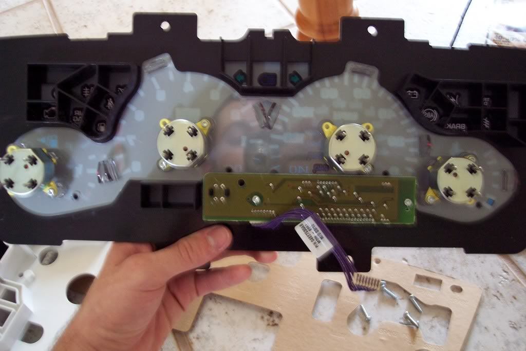
- Is there room behind that plate to mount the number blocks
- Can you actually remotely mount these little things (they have like 6 pins in the back of each one connected to the board)
- Is there enough room to fit the whole board behind there? (so I don't need to go solder crazy)
- And how friggen stupid am I for thinking this?
I tried to do a google search to see if anyone else has remote mounted those little block thingies, but 'block thingies' doesn't really come up with...promising results.
For reference, this is what the circuit boards look like in the AEM UEGO gauge:

And the space I'm looking to remodel (the plastic box just left of the odometer circuit board):