My Actron tells me:
Cam position sensor
A Bank 1 Ckt Malfunction.
Where is it, and can it be replaced easily?
Just got a call about a check engine light, scanned my mothers car, and viola. She said it took 2 tries to start it as well, which is obviously the sensor.
Thanks again guys!
P0340 Need a little advice
-
occasional demons
- Junior Admin
- Posts: 20306
- Joined: Thu May 03, 2007 12:14 pm
- Location: Ashland Ohio
Bill
1999 neon coupe 2.4 swap
2021 Forester
2000 Neon MTX swap with '02 R/T PCMOlha Koba, a psychologist in Kyiv, said that “anger and hate in this situation is a normal reaction and important to validate.” But it is important to channel it into something useful, she said, such as making incendiary bombs out of empty bottles.
1999 neon coupe 2.4 swap
2021 Forester
-
2003NeonSXT
- 2GN Member
- Posts: 117
- Joined: Tue Jul 05, 2011 6:05 pm
-
stdlystdmufn
- 2GN Member
- Posts: 1019
- Joined: Sun Feb 19, 2006 7:29 pm
- Location: Indianapolis, IN
- Contact:
i don't know where he got the description from bc bank 1 doesn't make sense to me with a CMP circuit either. but bank 1 does not actually only apply to O2 sensors. it actually refers to left and right banks of a multi bank engine. our 4 cyl (and most others) are inline so there is only 1 row of pistons all in line with each other. but a v-block or horizontally opposed (subaru) engines have two rows of pistons. the rows are called left and right or 1 and 2. typically on a v-block the forward most bank houses cylinder 1 so it is called bank 1 and the o2 sensor in that banks exhaust is call the bank 1 sensor. Also OBD2 codes are not car specific. they aren't even make specific. they are USDM (US domestic market/cars sold for use in the US) specific. so that is why an o2 sensor code on any inline engine sold in the US will be a bank 1 o2 fault (then up or downstream of the cat of course).2003NeonSXT wrote:Why would it say it's a Bank 1? Thought that referred to the upstream O2 Sensor?
so sense our cars only have 1 cmp sensor you just ignore the bank1 or circuit A in the description

in the middle of a DOHC and MTX swap and going with an ASP kit pwered by the S259 batmowheel
-
Antichrist
- n00b
- Posts: 10
- Joined: Mon Jul 30, 2012 6:01 pm
Sorry, I did NOT search before posting that, I was already up late to scan it, so yes.. I pulled a noob move on that one. 
Here's a picture of the readout so you don't think I'm a dildo for saying bank 1 etc..
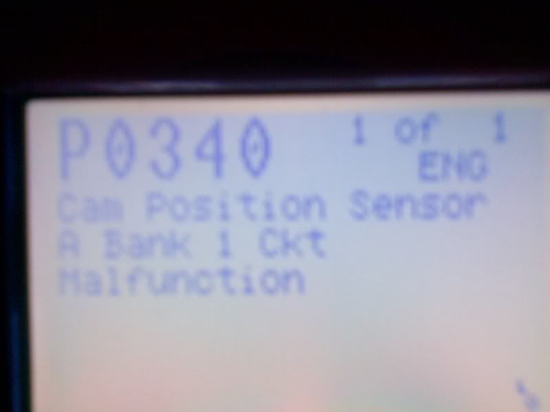
I agree that Bank 1 usually refers to O2 BS, but wasn't sure if neons had more than one cam sensor or whatever. I'm new to working on Chrysler products.
Thanks x100. I have to get this fixed before She goes in to work today at 1. Advance opens at 9. And we're supposed to have a wicked rain/wind storm, and my garage is full. FUN!
Here's a picture of the readout so you don't think I'm a dildo for saying bank 1 etc..
I agree that Bank 1 usually refers to O2 BS, but wasn't sure if neons had more than one cam sensor or whatever. I'm new to working on Chrysler products.
Thanks x100. I have to get this fixed before She goes in to work today at 1. Advance opens at 9. And we're supposed to have a wicked rain/wind storm, and my garage is full. FUN!
-
stdlystdmufn
- 2GN Member
- Posts: 1019
- Joined: Sun Feb 19, 2006 7:29 pm
- Location: Indianapolis, IN
- Contact:
ignore all the DRB and lab scope stuff (unless you own a lab scobe) so basically start at step 4. if you don't find a problem from step 4 on then it is probably your sensor. or you could just read the post that OD linked to.
Symptom:
P0340-CAMSHAFT POSITION SENSOR CIRCUIT
When Monitored: Engine cranking/running. Battery voltage greater than 10 volts
.
Set Condition: At least 5 seconds or 2.5 engine revolutions have elapsed with crankshaft
position sensor signals present but no camshaft position sensor signal.
POSSIBLE CAUSES
INTERMITTENT CRANKSHAFT POSITION SENSOR SIGNAL
INTERMITTENT CAMSHAFT POSITION SENSOR SIGNAL
(K7) 5 VOLT SUPPLY CIRCUIT SHORTED TO GROUND
(K7) 5 VOLT SUPPLY CIRCUIT OPEN
(K7) 5 VOLT SUPPLY CIRCUIT SHORTED TO VOLTAGE
(K44) CMP SIGNAL CIRCUIT SHORTED GROUND
(K44) CMP SIGNAL CIRCUIT OPEN
(K44) CMP SIGNAL CIRCUIT SHORTED TO VOLTAGE
(K44) CMP SIGNAL SHORTED TO (K7) 5 VOLT SUPPLY CIRCUIT
(K4) SENSOR GROUND CIRCUIT OPEN
PCM - (K7) 5 VOLT SUPPLY
PCM - (K44) CMP SIGNAL
CAMSHAFT POSITION SENSOR
TEST ACTION APPLICABILITY
1 Start the engine.
With the DRBIIIt, read the CMP SYNC State.
Does the DRBIIIt display the CMP SYNC State IN SYNC?
All
Yes ! Go To 2
No ! Go To 4
2 Turn the ignition off.
With the DRBIIIt lab scope probe and the Miller special tool #6801, back probe the
(K24) CKP signal circuit in the CKP harness connector.
WARNING: WHEN THE ENGINE IS OPERATING, DO NOT STAND IN A
DIRECT LINE WITH THE FAN. DO NOT PUT YOUR HANDS NEAR THE
PULLEYS, BELTS OR FAN. DO NOT WEAR LOOSE CLOTHING.
Ignition on, engine not running.
Wiggle the related wire harness and lightly tap the Crankshaft Position Sensor.
Observe the lab scope screen.
Start the engine.
Allow the engine to idle.
Observe the lab scope screen.
Did the CKP Sensor generate any erratic pulses?
All
Yes ! Repair as necessary.
Perform POWERTRAIN VERIFICATION TEST VER - 5.
No ! Go To 3
3 Turn the ignition off.
With the DRBIIIt lab scope probe and the Miller special tool #6801, backprobe the
(K44) CMP Signal circuit in the CMP harness connector.
WARNING: WHEN THE ENGINE IS OPERATING, DO NOT STAND IN A
DIRECT LINE WITH THE FAN. DO NOT PUT YOUR HANDS NEAR THE
PULLEYS, BELTS OR FAN. DO NOT WEAR LOOSE CLOTHING.
Ignition on, engine not running.
Wiggle the related wire harness and lightly tap on the Camshaft Position Sensor.
Observe the lab scope screen.
Start the engine.
Allow the engine to idle.
Observe the lab scope screen.
Did the CMP Sensor generate any erratic pulses?
All
Yes ! Repair as necessary.
Perform POWERTRAIN VERIFICATION TEST VER - 5.
No ! Test Complete.
4 Turn the ignition off.
Disconnect the CMP Sensor harness connector.
Ignition on, engine not running.
Measure the voltage of the (K7) 5 Volt Supply circuit in the CMP Sensor harness
connector.
Is the voltage between 4.5 and 5.5 volts?
All
Yes ! Go To 5
No ! Go To 13
5 Turn the ignition off.
Disconnect the CMP Sensor harness connector.
Ignition on, engine not running.
Measure the voltage of the (K44) CMP Signal circuit in the CMP Sensor harness
connector.
Is the voltage between 4.5 and 5.0 volts?
All
Yes ! Go To 6
No ! Go To 8
6 Turn the ignition off.
Disconnect the CMP Sensor harness connector.
Disconnect the PCM harness connector.
CAUTION: DO NOT PROBE THE PCM HARNESS CONNECTORS. PROBING
THE PCM HARNESS CONNECTORS WILL DAMAGE THE PCM TERMINALS
RESULTING IN POOR TERMINAL TO PIN CONNECTION. INSTALL
MILLER SPECIAL TOOL #8815 TO PERFORM DIAGNOSIS.
Measure the resistance of the (K4) Sensor Ground circuit from the CMP Sensor
harness connector to the appropriate terminal of special tool #8815.
Is the resistance below 5.0 ohms?
All
Yes ! Go To 7
No ! Repair the open in the (K4) Sensor Ground circuit.
Perform POWERTRAIN VERIFICATION TEST VER - 5.
7 NOTE: Inspect the Camshaft sprocket for damage per the Service
Information.
If a problem is found repair as necessary.
If there are no possible causes remaining, view repair.
All
Repair
Replace the Camshaft Position Sensor.
Perform POWERTRAIN VERIFICATION TEST VER - 5.
8 Turn the ignition off.
Disconnect the CMP Sensor harness connector.
Disconnect the PCM harness connector.
Measure the resistance between ground and the (K44) CMP Signal circuit in the
CMP Sensor harness connector.
Is the resistance below 100 ohms?
All
Yes ! Repair the short to ground in the (K44) CMP Signal circuit
Perform POWERTRAIN VERIFICATION TEST VER - 5.
No ! Go To 9
9 Turn the ignition off.
Disconnect the CMP Sensor harness connector.
Disconnect the PCM harness connector.
CAUTION: DO NOT PROBE THE PCM HARNESS CONNECTORS. PROBING
THE PCM HARNESS CONNECTORS WILL DAMAGE THE PCM TERMINALS
RESULTING IN POOR TERMINAL TO PIN CONNECTION. INSTALL
MILLER SPECIAL TOOL #8815 TO PERFORM DIAGNOSIS.
Measure the resistance of the (K44) CMP Signal circuit from the CMP Sensor
harness connector to the appropriate terminal of special tool #8815.
Is the resistance below 5.0 ohms?
All
Yes ! Go To 10
No ! Repair the open in the (K44) CMP Signal circuit.
Perform POWERTRAIN VERIFICATION TEST VER - 5.
10 Turn the ignition off.
Disconnect the CMP Sensor harness connector.
Ignition on, engine not running.
Measure the voltage of the (K44) CMP Signal circuit in the CMP Sensor harness
connector.
Is the voltage above 5.2 volts?
All
Yes ! Repair the short to battery voltage in the (K44) CMP Signal
circuit.
Perform POWERTRAIN VERIFICATION TEST VER - 5.
No ! Go To 11
11 Turn the ignition off.
Disconnect the CMP Sensor harness connector.
Measure the resistance between the (K44) CMP Signal circuit and the (K7) 5 Volt
Supply circuit in the CMP Sensor harness connector.
Is the resistance below 5.0 ohms?
All
Yes ! Repair the (K44) CMP Signal circuit shorted to the (K7) 5 Volt
Supply circuit.
Perform POWERTRAIN VERIFICATION TEST VER - 5.
No ! Go To 12
12 NOTE: Before continuing, check the PCM harness connector terminals for
corrosion, damage, or terminal push out. Repair as necessary.
If there are no possible causes remaining, view repair.
All
Repair
Replace and program the Powertrain Control Module in accordance
with the Service Information.
Perform POWERTRAIN VERIFICATION TEST VER - 5.
13 Turn the ignition off.
Disconnect the CMP Sensor harness connector.
Disconnect the PCM harness connector.
Measure the resistance between ground and the (K7) 5 Volt Supply circuit in the
CMP Sensor harness connector.
Is the resistance below 100 ohms?
All
Yes ! Repair the short to ground in the (K7) 5 Volt Supply circuit.
Perform POWERTRAIN VERIFICATION TEST VER - 5.
No ! Go To 14
14 Turn the ignition off.
Disconnect the CMP Sensor harness connector.
Disconnect the PCM harness connector.
CAUTION: DO NOT PROBE THE PCM HARNESS CONNECTORS. PROBING
THE PCM HARNESS CONNECTORS WILL DAMAGE THE PCM TERMINALS
RESULTING IN POOR TERMINAL TO PIN CONNECTION. INSTALL
MILLER SPECIAL TOOL #8815 TO PERFORM DIAGNOSIS.
Measure the resistance of the (K7) 5 Volt Supply circuit between the CMP Sensor
harness connector and the special tool #8815 terminal.
Is the resistance below 5.0 ohms?
All
Yes ! Go To 15
No ! Repair the open in the (K7) 5 Volt Supply circuit.
Perform POWERTRAIN VERIFICATION TEST VER - 5.
15 Turn the ignition off.
Disconnect the CMP Sensor harness connector.
Ignition on, engine not running.
Measure the voltage of the (K7) 5 Volt Supply circuit in the CMP Sensor harness
connector.
Is the voltage above 5.5 volts?
All
Yes ! Repair the short to battery voltage in the (K7) 5 Volt Supply
circuit.
Perform POWERTRAIN VERIFICATION TEST VER - 5.
No ! Go To 16
16 NOTE: Before continuing, check the PCM harness connector terminals for
corrosion, damage, or terminal push out. Repair as necessary.
If there are no possible causes remaining, view repair.
All
Repair
Replace and program the Powertrain Control Module in accordance
with the Service Information.
Perform POWERTRAIN VERIFICATION TEST VER - 5.
in the middle of a DOHC and MTX swap and going with an ASP kit pwered by the S259 batmowheel
-
Antichrist
- n00b
- Posts: 10
- Joined: Mon Jul 30, 2012 6:01 pm
Holy info! Thanks Stdly.
I've got a wicked storm coming so I'm going to skip the diagnostics for now, and just assume the sensor is bad. She didn't have any issues until last night, so I'm assuming the intermittent problem is the sensor, and not an open/short in the wiring. If I'm wrong, I'll proceed to diagnose the circuit and find any other problems that may exist.
And I'll have to buy a new pigtail too. Couldn't figure out the goddamn thing for the life of me, and ended up breaking 3 pieces off lol. I pushed that red retainer and it didn't budge. The plastic was brittle as hell, so I'm assuming it's the original.
Also, it appears that on the 2003, they changed some of the bolt sizes as follows:
3/8" wasn't used on the battery tray, only the 10mm and 13mm. I suggest a deepwell for the 2 battery tray nuts nearest to the firewall.
And I used an 8mm (IIRC), instead of the suggested 1/4" to remove the CPS.
I only needed to remove the top hose/clamp to remove the top bolt nearest the firewall. I was able to easily work around the hoses otherwise.
And the first step for me was to remove the sensor at the intake elbow, and unbolt the airbox so I had enough wiggle room to get to the front 3 battery tray bolts. What a PITA. I need to get her a cone filter.
-
Antichrist
- n00b
- Posts: 10
- Joined: Mon Jul 30, 2012 6:01 pm
Ok job complete. Thank you all x10.
New pigtail was in stock at another Advance nearby, so I took a cruise over and replaced the harness as well as the sensor.
The car seems to turn over a little faster than before. Maybe it's just a mental thing.. new parts, and I think it starts better, but It works, and I beat the storm
New pigtail was in stock at another Advance nearby, so I took a cruise over and replaced the harness as well as the sensor.
The car seems to turn over a little faster than before. Maybe it's just a mental thing.. new parts, and I think it starts better, but It works, and I beat the storm
-
occasional demons
- Junior Admin
- Posts: 20306
- Joined: Thu May 03, 2007 12:14 pm
- Location: Ashland Ohio
When the connector gets brittle, and the lever snaps, so the latch end does not release, a 90º pick is your best friend. Just slip the end under the latch and lift while pulling gently on the connector. All of my injector connectors require this method.
The solenoid connector on my stater is also a permanent part of the assy. I put a different connector at the IM so I can just unhook it there. Easier than fighting with it, from underneath the IM.
Just for future reference.
A cheap pick set can be had at Wally Mart for ~$4. They work well for the above purpose, and are cheaper than new connector ends/time to cut/solder, etc. Be sure you solder/shrink tube the connections, Or you may get more signal problems down the road.
Bill
1999 neon coupe 2.4 swap
2021 Forester
2000 Neon MTX swap with '02 R/T PCMOlha Koba, a psychologist in Kyiv, said that “anger and hate in this situation is a normal reaction and important to validate.” But it is important to channel it into something useful, she said, such as making incendiary bombs out of empty bottles.
1999 neon coupe 2.4 swap
2021 Forester